
-
TnT Plus
TnT Plus
TnT+ Test Function Flow Chart
Please Note: Menu 1 is common to all models (TnT, TnT-el & TnT+)
TnT+ Test Function Flow Chart
Menu 2
 +
+ Menu 2
F1 Power Test F2 Leakage Test F3 RCD Test


Menu 2
F1 Power Test
Instructions for Power Test:
F1+ F3 = Power Results

Appliance Power
Test Continue if Safe? Ok/Quit

Power Results
240V 0W
0.000A 0VA
0.00PF

To return to Menu
2 press return

Menu 2
F2 Leakage Test
Instructions for Leakage Test for: Earthed Devices: F2+ F1+ F3 = Results
D/Ins: F2+ F2+ F3 = Results
RCD Protected: F2+ F3+ F3 = Results
Leakage Test
(F1) Earthed Devices
Earth Leakage Test
Continue if Safe?
Ok/Quit
Leakage Results
Pass <5.0mA
0.0mA Pass/Esc
Emergency Stop
Abort
To return to Menu 2 press Return
Leakage Test
(F2) D/Ins Devices
Earth Leakage Test
Continue if Safe?
Ok/Quit
Leakage Results
Pass <1.0mA
0.0mA Pass/Esc
Leakage Test
(F3) RCD
Earth Leakage Test
Continue if Safe?
Ok/Quit
Leakage Results
Pass <2.5mA
0.2mA Pass/Esc
Menu 2
RCD Test
Instructions for RCD Test for:
Time Test
0' Phase: F3+ F1+F1+ F3 = Results
180' Phase: F3+ F1+ F2+ F3 = Results Change Current: F3+ F1+ F3+ F3= Setting
Ramp Test: F3+ F2+ F3 = Result
RCD Tests
(F1) Time Test
Timed Test 30mA
(F1) 0' Phase
(F2) 180' Phase
RCD Multiplyer
(F3) Start
RCD Timed Test
Time: 4ms
Timed Test 30mA
(F3) Change Current
RCD Test Current
(F3) Set
RCD Test
Current
Saving Settings
RCD Tests
(F2) Ramp Test
RCD Ramp Test
(F3) Start
RCD Ramp Test
Testing
RCD Ramp Test
Time 4ms
Tests Common To All Models - Main menu A
Earthed Appliance Test (refer to TNT - Series)
Double Insulation Test (refer to TNT - Series)
Lead Test (Ext Lead Test) (refer to TNT - Series)
Power Test - Main menu B
The Power Test is for the purposes of monitoring and performance testing up to the current value 10Amps.
Please Note: A Visual Inspection test must be carried out before any others (refer to First Test Section)
The Power TEST completes the following sequence as part of its comprehensive testing procedure:
1. Integrated Supply Mains Test
Refer to Integrated Test section
2. Power Test
Procedure:
- Complete a Visual Inspection. For details refer to the First Test section. If the unit passed the Visual Inspection, continue with the following instructions. If not, refer to the First Test section.
- Plug male end of appliance into TNT - Series Appliance socket.
- Press F1 to start the power test.
- If the appliance is safe to test press F3 on safety warning message. The unit will power on.
- Read and record results appropriately.
- Once the appliance has powered down and the test is complete. Unplug the unit.
- Press Enter to return to the main menu.
This test is ideal for service agents and electricians. The user can plug in the appliance and turn it on with real time measurements displayed on the display. This is useful when testing an appliance with a compliance/name plate on it. The operator can compare the name plate details of operating voltage, operating current, and power factor etc. should the appliance exceed the said values on the name plate it could be deemed faulty and require service.
Please note: Because the power test is not required in the electrical testing standards there is no pass / fail value in the TnT+. It is up to the user to determine if the item is a pass or a fail based on the compliance/name plate.
If the result was a pass - Tag with the appropriate tag including "next test due" date and "return to service".
If the result was a fail - Tag with a DANGER TAG and remove the unit from service.
The Power Test allows the user to turn the appliance on and measure its performance as a digital watt meter. Displayed parameters are:
- Volts AC
- Current
- Volt Amp
- Power Factor
- Watts

Caution: Before operating ensure the equipment is firmly secured to eliminate the possibility of causing injury or damage. This function turns powers the Unit on, Please make sure the drills or any blades of any rotating devices have been removed prior to any testing and have clearance from body or object. Appliances may jump off benches and may need to be secured by clamping them, or they may cause serious damage if not secured properly.
RCD Test - Main menu B
Please Note: Where ANY RCD testing, is to be carried out any circuit that is protected by an RCD in the main switchboard (upstream), it’s most likely to trip this upstream RCD. When performing RCD trip time or Ramp current tests on any (portable) RCD devices, the RCD in the switchboard may trip faster. This is due to increased upstream levels of leakage current from the additional circuits and devices connected to it. The fixed RCD’s can also have better connectivity, sensitivity and mechanical mechanisms.
To avoid tripping large areas in the work place monitored by the switchboard RCD it is suggested that an RCD (Isolation Transformer) be used. These are designed specifically for the purposes of field RCD tripping.
DO NOT use these Transformers for any other purpose.
Ratings 240VAC in 240VAC Out @ 30VA Fuse protected Primary winding 500mA
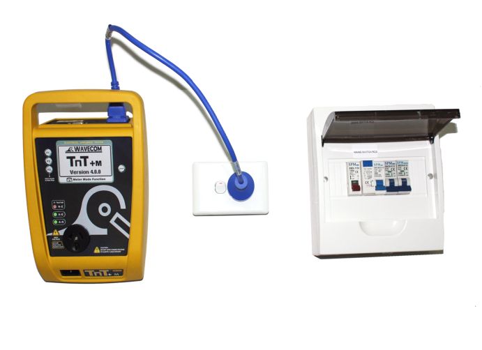
To perform RCD tests the TnT+ supply lead needs to be plugged in to the RCD device to be trip tested. For tripping switchboard mounted (Fixed) RCDs Plug TnT+ into GPO marked RCD protected or if known to be protected circuit. (Diagram 2)
(Isolation Transformer Required) If testing portable RCD devices on power boards or extension leads plug TnT+ into power board or lead (Isolation Transformer Required) Diagram 1
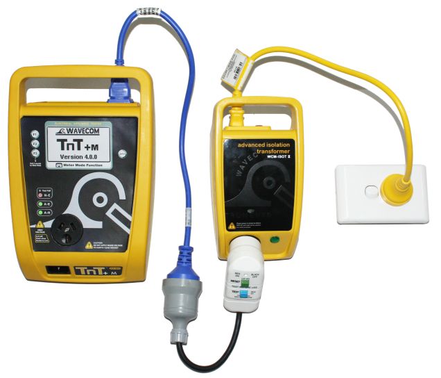
Diagram 2 For Testing Fixed RCD at Switchboard
To do this test select the second menu, press and release the Return/Enter button.
This menu will now display 3 functions:
- Power Test
- Leakage Test
- RCD Test
To enter the RCD menu press and release the F3 button.
RCD Tests
Time Test
Ramp Test
ExitPress F1 to select the time test.
Trip Time Testing: This principal is designed to trip RCD devices at a fixed current and to determine the trip time of the RCD device.
This function is factory set to 30mA for fast testing the user can set the current to X0.5, X1.0, X 5 using the RCD Multiplier.
I.E. 30mA X 0.5 =15mA
30mA X 1.0 = 30mA (this also is effective on any set test current of the RCD tester from 5mA to max 500mA output.)
30mA X 5.0 = 150mA
These tests should result in no-trip, trip & fast trip times respectively.
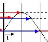
F1 - 0 deg
This is the positive half of the mains supply cycle. (50HZ Aust/NZ). Press F1 – The preset mA test current will then be used in the following test and begin the trip test from the positive half of the sine wave.
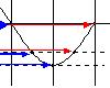
F2 - 180 deg
This is the negative half of the mains cycle, (50HZ Aus/NZ). Press F2 - The preset mA test will then be used in the following test and begin the trip test in the negative half of the sine wave.
Performing a Time Test:
The displayed trip time is in milliseconds. This is the time taken for the RCD device to trip once the injected fault current has been applied. The TnT+ injects a true fault current value using a real time compensation calculation of the actual voltage at the time of test hence delivering a true and accurate trip current.
Timed Test 30mA
0 Deg.
180 Deg
SettingsRCD Test Options:
F3 – Change to select tested: This allows the user to set the trip current level, 5mA to 500mA. The RCD type can also be select here depending whether the unit is a type I or type II. See the next section for explanation. From the options menu press F2 to change the current level and F3 to change the RCD type.
Options:
Set Current
Set RCD TypeAdjusting the current level:
The TnT displays and maintains the last, set trip current value.
If the user wishes to change the value of the trip current the following steps enable the changes:
Press and release F2 from the options section to display test current.
Up - This button raises the trip current in 1mA increments to 500mA. Hold the button and the value will scroll faster the longer depressed. Once 500mA limit is reached the value will then loop over and start again from 0mA
Down - This button decreases the trip current in 5mA increments. Hold the button and the value will scroll faster the longer depressed. Once 0mA limit is reached the value will then loop over and start again from 500mA.
Set - This button sets the selected current for the next trip time test. The TnT+ will then return to the current trip time test screen.
Changing the RCD type:
Depending on the RCD, the RCD type needs to be selected from the options menu. These options change the pass / fail values when performing RCD tests. Please make sure that you have the correct RCD type selected. The RCD types are:
Type I:
Has a trip time of < 40mS and a trip current of < 10mA. These types of RCD's are mainly used on sites containing medical equipment. These types of RCD's must be compliant with AS3551.Type II:
Has a trip time of < 300mS and a trip current of < 30mA. Unless specified on the RCD device nearly all RCD will be this type. This is the default setting on new units.Selects type I and saves to memory
Selects type II and saves to memory
RCD Timed Test (continued):
Press the F1 key to select the 0 deg test and the F2 key to select the 180 deg test.
Use the F1/F2 keys to scroll through the multipliers X0.5 X1.0 X5.0 of the set current.
Maximum output current = 500mA. I.E if set test current were 100mA then 100 X 5.0 =500mA.
If set test current = 200mA then maximum output 5 x 200mA =1A is out of range. Unit will not deliver this output current and display on Screen “OUT of RANGE”.
Press F3 to start test. TnT will display results for 5 seconds after mains supply is tripped. If the power is not reset by the time the unit loses power then the result will be displayed on power on.
Caution: Pressing F3 at this point will cause tripping if RCD fitted to circuit
RAMP CURRENT TEST. This testing principal is designed to trip RCD devices using a ramping up current value, to determine the trip current of the RCD device. This useful test allows the user to determine circuit leakage load/pre-loading of RCD circuit. This can assist in determining nuisance tripping issues or determining RCD performance if suspected faulty or inconsistent in performance. The TnT has a nominal leakage current of 2mA, which should be added to the result of test. E,G. if RCD tripped at 22mA + 2mA(TnT+)=24mA trip current.
RCD Trip Current. Press F2 to show the Trip current screen.
RCD Ramp Test:
Set RCD Type
Start ExitCaution: Pressing F3 at the RCD ramp test screen will cause tripping if RCD fitted to circuit. F2 can be pressed to change the RCD type at this point. See "Changing the RCD type" for details.
The Trip Current Test will ramp the mA current up until the RCD breaker trips. Current range 2.55 - 500mA. This test can go for up to 10 sec to scroll through full range if RCD faulty or not fitted. Repeated testing in this mode will cause heating of TnT. Should over heating occur the internal temperature sensor will cause display to indicate “over temp allow to cool” This requires the TnT device to be best left unplugged for several minutes allowing unit to cool.
TnT will display results for 5 seconds after mains supply is tripped. If the power is not reset by the time the unit loses power then the result will be displayed on power on.
Caution: Continuous ramp current testing will cause unit to over heat
TnT Plus